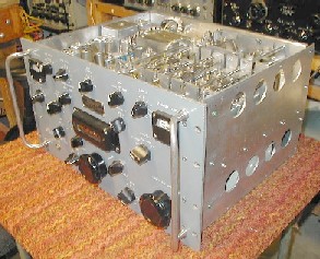
Stewart Warner R390A Rebuild

Picked this up on ebay back in March 2004. Tag says it's a Stewart Warner serial number 43. I spent about two years rebuilding this unit, module by module. I didn't do it all contiguously, I'd do a module, then work on some other project, then come back to this and do the next module. Thus it took a couple years to complete. But boy is it a beautiful radio. It's a marvel of both electronics engineering and mechanical engineering. probably one of the best HF receivers ever made. We had a couple of these on the USS San Jose when I served aboard. We never really had to do anything to these radios. They just worked all the time. Actually we were a little intimidated by the mechanicals at the time. I remember it looking like a Swiss watch or an automatic transmission or something. None of us wanted to mess with that. But not anymore. I tore this one all the way down and rebuilt it. Not really all that intimidating at all.
Here are the original pictures of the unit. These were right off of ebay. This is how it looked when I got it. Underside looked great. The top however was pretty dirty. I never did fire it up before rebuild. I heard to many horror stories about bad caps taking other things out like mechanical filters.

The first module I did was the power supply. However, I lost all the power supply pictures when transferring them from one computer to another. Windows did that for me, thank you Microsoft. So I don't have any pics of the power supply rebuild. Next module I did was the Audio Deck.


AF Deck

Above pics are disassembly. I completely took it down to a bare chasses.
Here it is finished, rebuilt. I replaced all the carbon comp resistors with new metal film resistors, I always do, the carbon comp resistor change value to much I don't trust them. I reused the original wiring harness. I did have a bad remote output transformer and had to get a replacement from Fair Radio. I also installed the AF LF Mods which involves changing several coupling cap values to improve the LF response. I did not do the 6AQ5 conversion. Next up is the IF Deck.

IF Deck

Above pics are prior to rebuild and coming apart. I did take it down to a bare chassis as I do. You can see those nasty BBOD's.
Here it is rebuilt. The components are really packed in there. It took quite a bit of planning, looking at pics, drawings, and the schematics to get the parts back in there. I again reused the original wiring harness. Again I replaced all the carbon comps with metal film resistors. All the caps were replaced. I installed the SSB AGC mods described by Lankford that involved adding diodes in parallel with R546 and R547 as well as adding a 47pfd cap in parallel with C535. By the way this unit receives SSB very well in my opinion. Once set it is very stable and requires almost no tuning adjustment to keep the audio legible. I really don't see the need for a product detector mod or add on to receive SSB with this receiver. One other thing of note. After washing the bare chassis with plain old soap and water I used finger nail polish to cover all the writing on the chassis. It preserved the chassis labeling very well when doing the bare chassis with fine steel wool. Ya I know. the steel wool does and did remove the anodizing. I also did the replacement of the S-Meter pot with a 10 turn pot.

Next up was the PTO. However, again these pics were lost when transferring them from one computer to another. Windows did that for me again, thank you Microsoft. So I don't have any pics of the PTO rebuild. Next time I have the radio apart I will take some pics of the completed PTO so I can at least put them up. After the PTO I did the 2nd LO.

2nd LO


The 2nd LO was pretty much uneventful. It was really pretty clean to begin with. I didn't take to many pictures as it's pretty straight forward. I took it down to a bare chasses, replaced all the carbon comp resistors, replaced some caps. I left the original mica's in as they all checked okay.
Here it is complete. I did find that I had some frequency error with the receiver when it was all complete and I was doing alignment. The PTO was spot on and I discovered that the error was coming from the 2nd LO. Turns out some of the crystals were slightly off frequency. Unfortunately it also turns out that adjusting the trimmers does not warp frequency, it only impacts amplitude of the frequency it is oscillating at. I did not fix this problem. Someday I do plan to get some crystals and change the offending ones and see if that corrects it. The error is small and for now I can live with it.

Next up was the chassis.


Chassis

Chassis was pretty uneventful as well. It was pretty dirty though. I did the front panel along with the chassis. I didn't do anything to the front panel but strip it down and wash it. Other than that I did not try refinishing the front panel. It looks pretty good. I did replace the selenium rectifier with a semiconductor bridge. I also discovered I had a shot antenna switch as well. Contacts were shot. I ended up getting a new ant switch, think I got it off ebay if I remember right. But other than that all I did was strip the chassis down, wash it, and then used fine steel wool to shine it up.
Here's the finished ant switch. This is the one I got off ebay, cleaned up very well and works good. Here's the completed chassis. You can see the bridge rectifier I put in to replace the selenium rectifier. I also used the original line filter, it checks and works fine. Next up, the RF deck.

RF Deck


Here's a few shots before digging into it. It was pretty dirty over all. The parts are really packed into the calibration osc section. And there's some of those ugly BBOD's.
Above shots are the deck coming apart. Took it down to a bare chasses. Replaced all the carbon comps with metal film. Replaced most caps, I did leave the micas in the coil sections, they seemed to be okay and checked good.
Here it is rebuilt. Really came out good, really shines. Performance is great. It aligned right up very nicely when finished. Next up the gear train.


Top Of Projects Page


Home