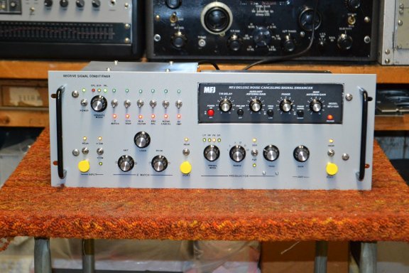
Receive Signal Conditioner


 I worked on this project on and off for several years finally completing it in December 2018. Many would say it's a bit overkill, and it is, but for me it's so cool, was fun to design and build, lots of knobs and switches and it is functional. I also needed a home for an MFJ-1026 Noise Canceling Signal Enhancer and this was the perfect project for that.

DESIGN REQUIREMENTS
1) Operating range .5 MHz - 32 MHz
2) Antenna input switchable between front panel and rear panel
3) Input signal level protection and antenna static build up protection
4) Modes of Operation to include
      A) Off Line (OFL) - Terminates the antenna input into 50 ohms, conditioner disconnected from the antenna
      B) Bypass (BYP) - Conditioner bypassed, input routed directly to the output
      C) In line (INL) - Conditioner inline
5) Z Matching - Switchable in line or bypassed - used to match the dynamic antenna impedance to the 50 ohm characteristic impedance used in the conditioner
6) 1220 Trap - Switchable in line or bypassed - used to help attenuate the pesty 1220 KHZ  WKRS BCB station nearby
7) BCB Filter - Switchable in line or bypassed - used to attenuate BCB signals to help improve image rejection
8) Pre Selector - Switchable in line or bypassed - with multiple configuration options to include operation as
      A) Low Pass Filter
      B) High Pass Filter
      C) Peaking using a series resonant ckt
      D) Peaking using a parallel resonant ckt
      E) Dipping using a series resonant ckt
      F) Dipping using a parallel resonant ckt
9) Noise Cancelling using the MFJ-1026 - Switchable in line or bypassed
10) RF Amp - Switchable in line or bypassed - used to compensate for insertion losses of the conditioner as well as provide some gain to the signal if desired
11) Service Port Points - Switchable between front panel and rear panel - used to provide access points along the signal path to connect test equipment for measurement and testing.


Designing The Conditioner

BLOCK DIAGRAM
The switchable input allows for a front panel access point for a second antenna or test equipment. The first service port was placed after the Z Match and the second service port was placed at the end of the signal path. This allows for testing of the conditioner circuits with the conditioner bypassed isolating the ckts from the antenna input.
INPUT CIRCUIT
A pair of 1N914 fast switching silicone diodes were used at each input to limit input signal level peaks to .6 volts and prevent overload of high level inputs. A 100K resistor is to bleed off any static that may develop on the antenna. A 51 ohm resistor terminates the antenna when the conditioner is switched off line (OFL). Off line also disconnects the output from the conditioner. This mode is usable with the conditioner powered up. This is the recommended position when the conditioner is not in use. The antenna coupling circuit provides a +12v control signal at the rear panel that can be routed to the antenna. The intent was to be able to switch between impedance matching baluns at the antenna depending on frequency range being received. One balun being used when below 10MHz and a different balun being used above 10MHz. This was based on a 100 foot end feed random wire antenna which has much higher dynamic impedance variations below 10 MHz vs. above 10 MHz. Having a different balun helped smooth the impedance variations of the two different ranges and this circuit was to enable switching baluns between them from the conditioner.
Z MATCH CIRCUIT
Purpose of this circuit is to match antenna impedance to the 50 ohm characteristic impedance of the conditioner. I use un-un baluns at the antenna and the feed line is 75 ohm coax to the listening site. This is an overkill item but I did it anyway. For receive the need to impedance match is considered by many to be a moot point as the signal levels are so low Z matching is negligible compared to high level RF from a transmitter. But hey, it added knobs and functions and I just couldn't get the phrase "Max power is transferred when impedances are matched" out of my head. I used a "T" configuration rather then a "pi" configuration because "T" configs work best at matching lower impedances and "pi" configs work better at matching higher impedances. Pretesting/piloting both types of circuits proved the "T" worked better. I did the value calculations using 75 ohm input to 50 ohm output.
1220 TRAP AND FIRST SERVICE PORT CIRCUIT
Purpose of this circuit is to attenuate a nearby 1KW Broadcast Band (BCB) AM Station WKRS at 1220 KHz from blowing through everything. An old Meisner 15-8481 Wave Trap was used. I have 5 of these in my spare parts so I figured I'd use one of them here. They are old and obsolete and can be configured in either a series or parallel configuration tunable between 950 KHz - 1600 KHz. I used the series config. It provides a peak dip of -5db at 1220 KHz with a 3db down BW of 20 KHz. The coupling to the first service port is also provided for at this point through a .1ufd coupling cap.
BCB FILTER CIRCUIT
Purpose of this circuit is to attenuate BCB signals which can create images and blocking from strong BCB signals. The design for this circuit came from ARRL Handbook - 1990 edition Pg. 30-24. It works very well, good design. It has a 3db down knee at 1.75 MHz and a 6db down knee at 1.70 MHz.
PRESELECTOR CIRCUIT - SIGNAL
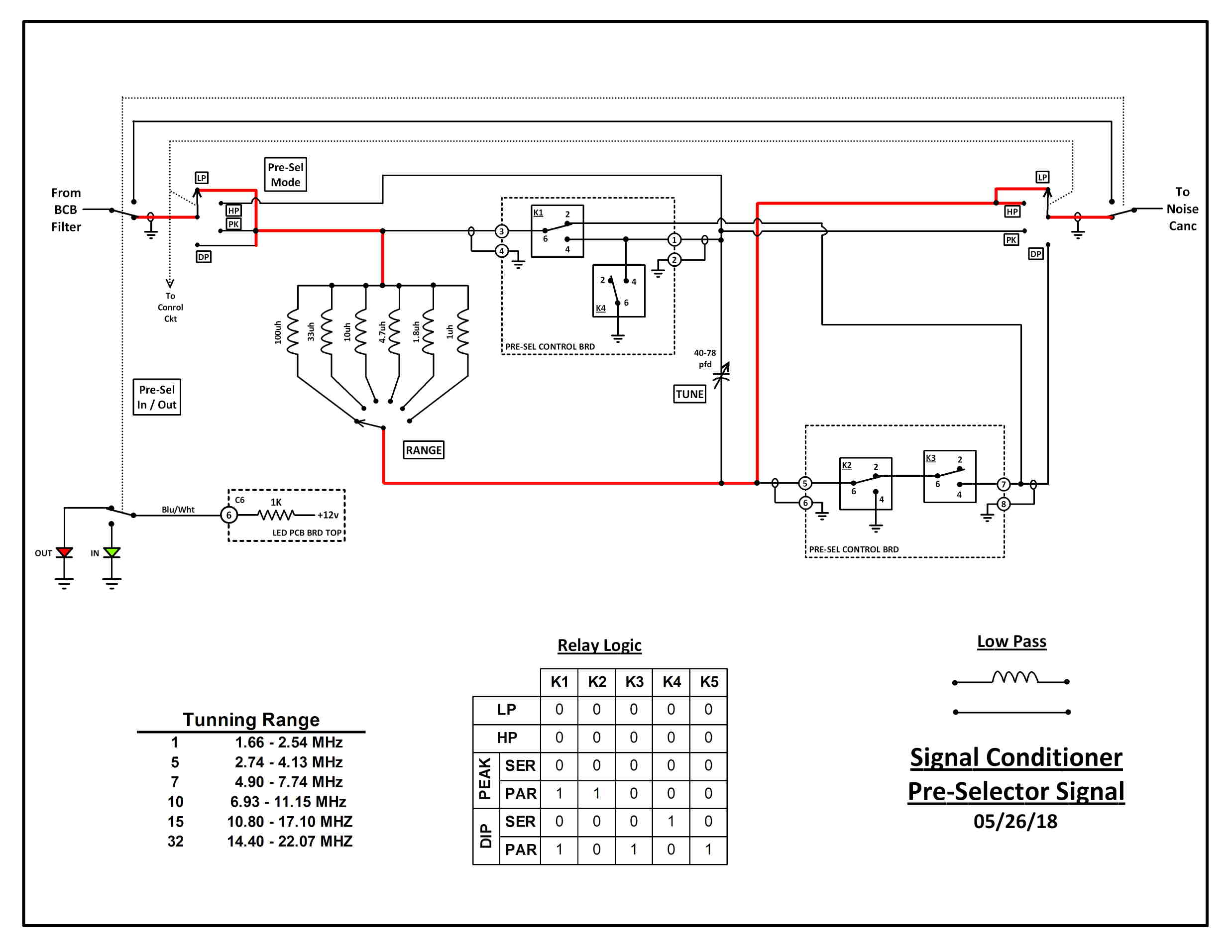
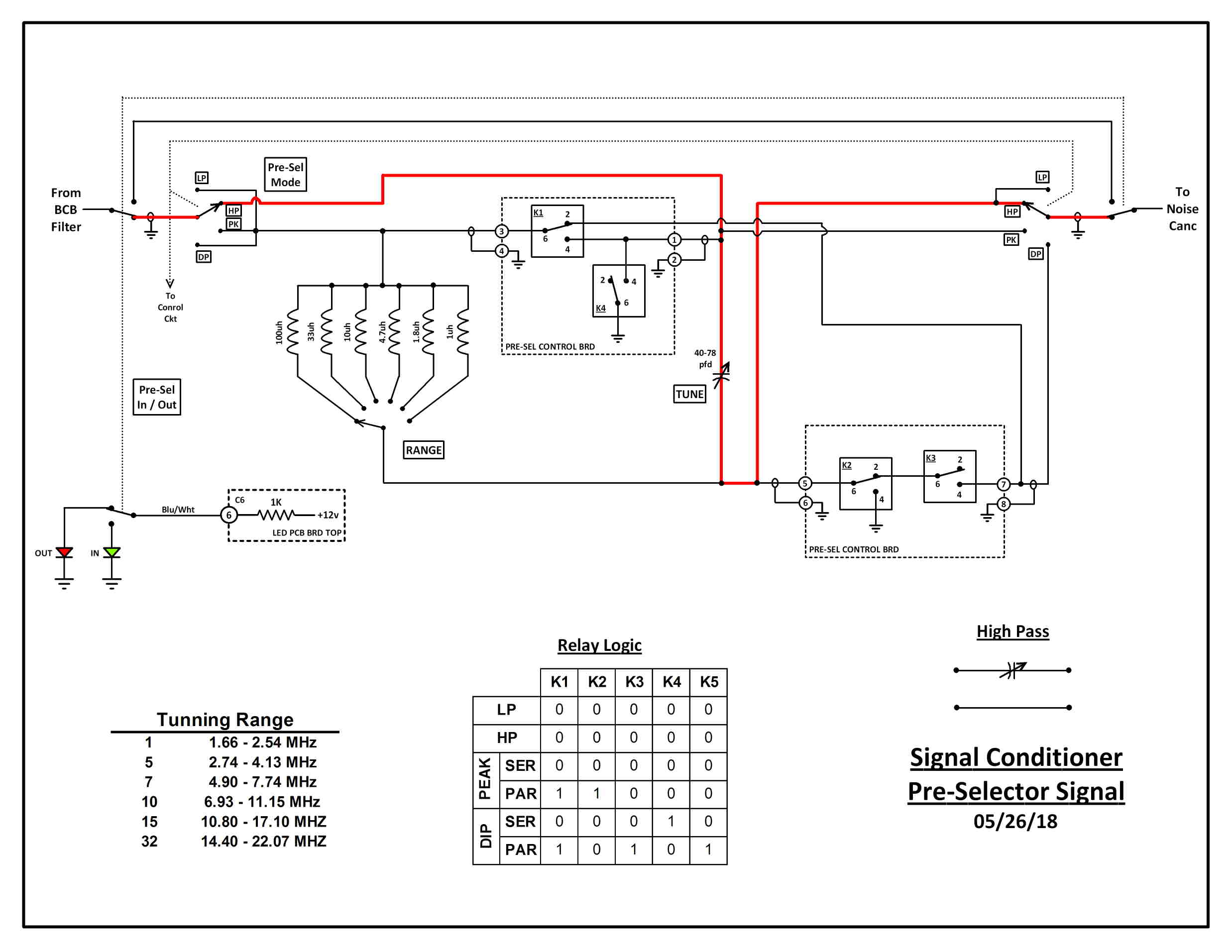
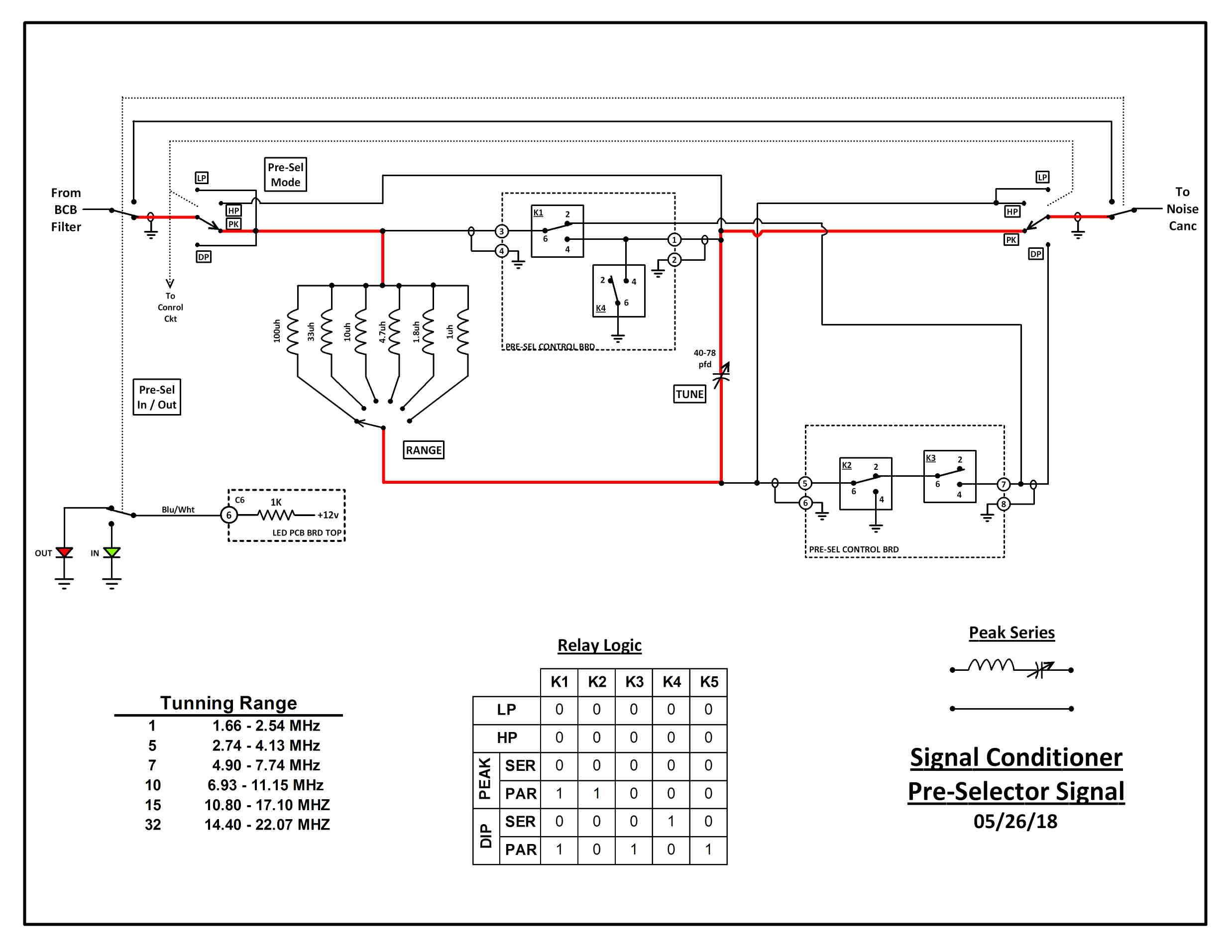
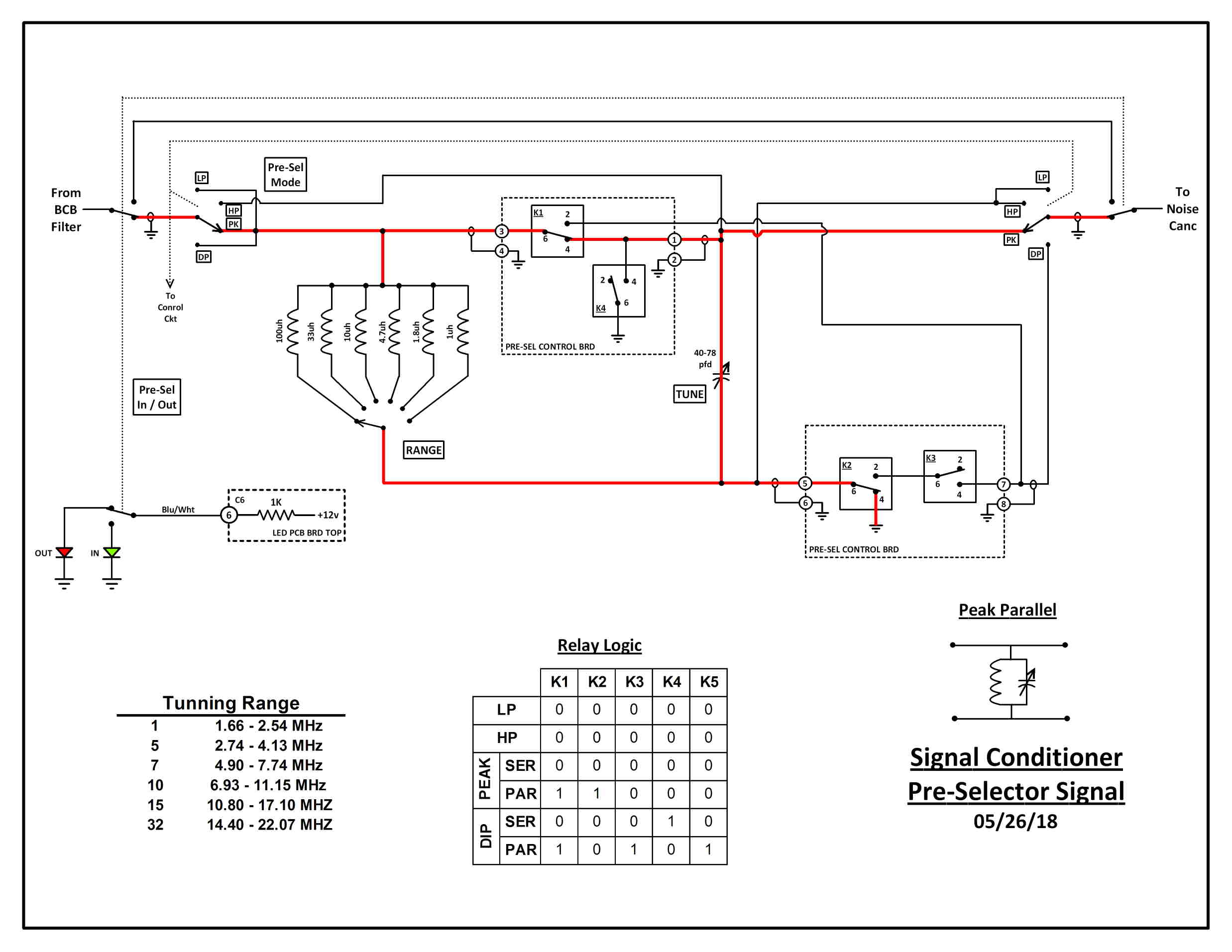
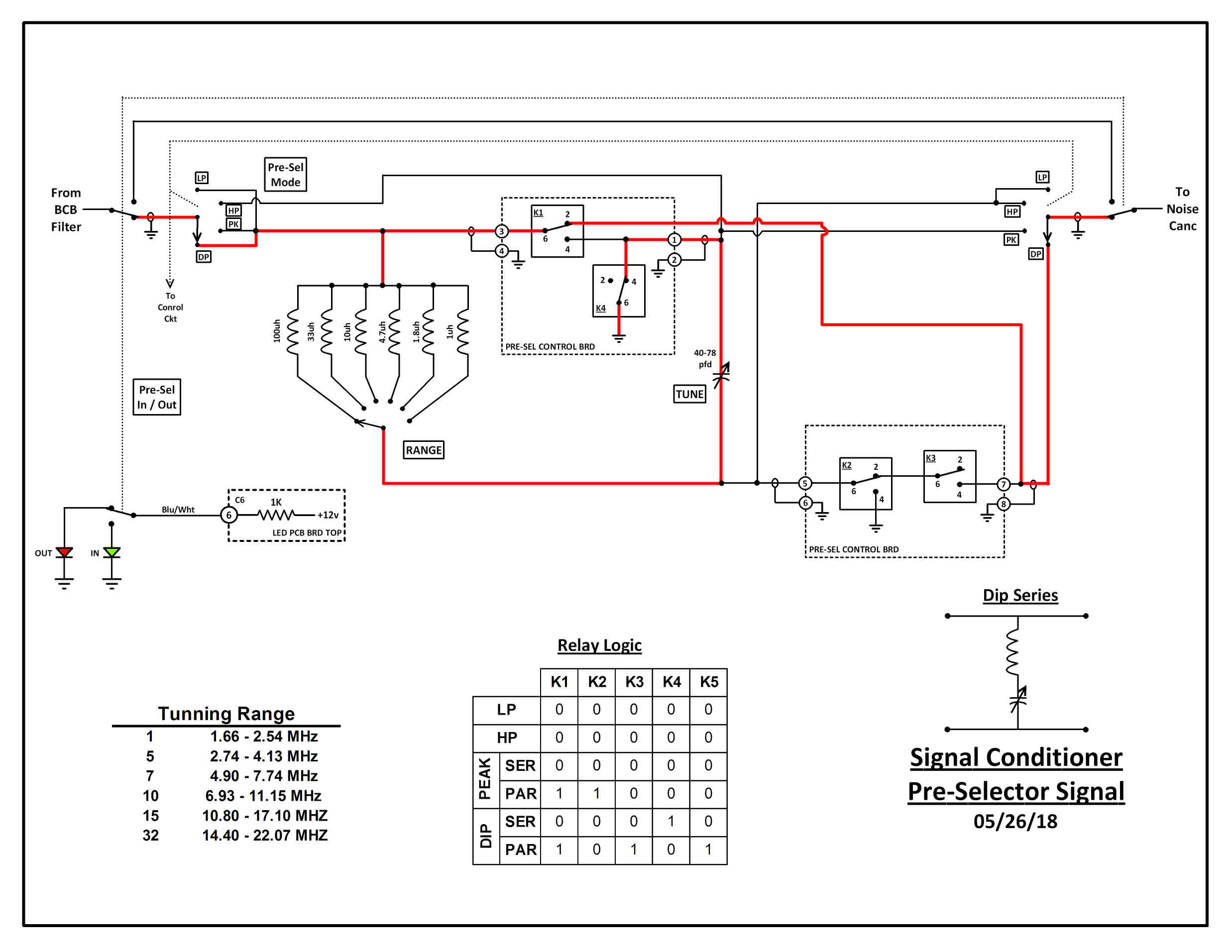
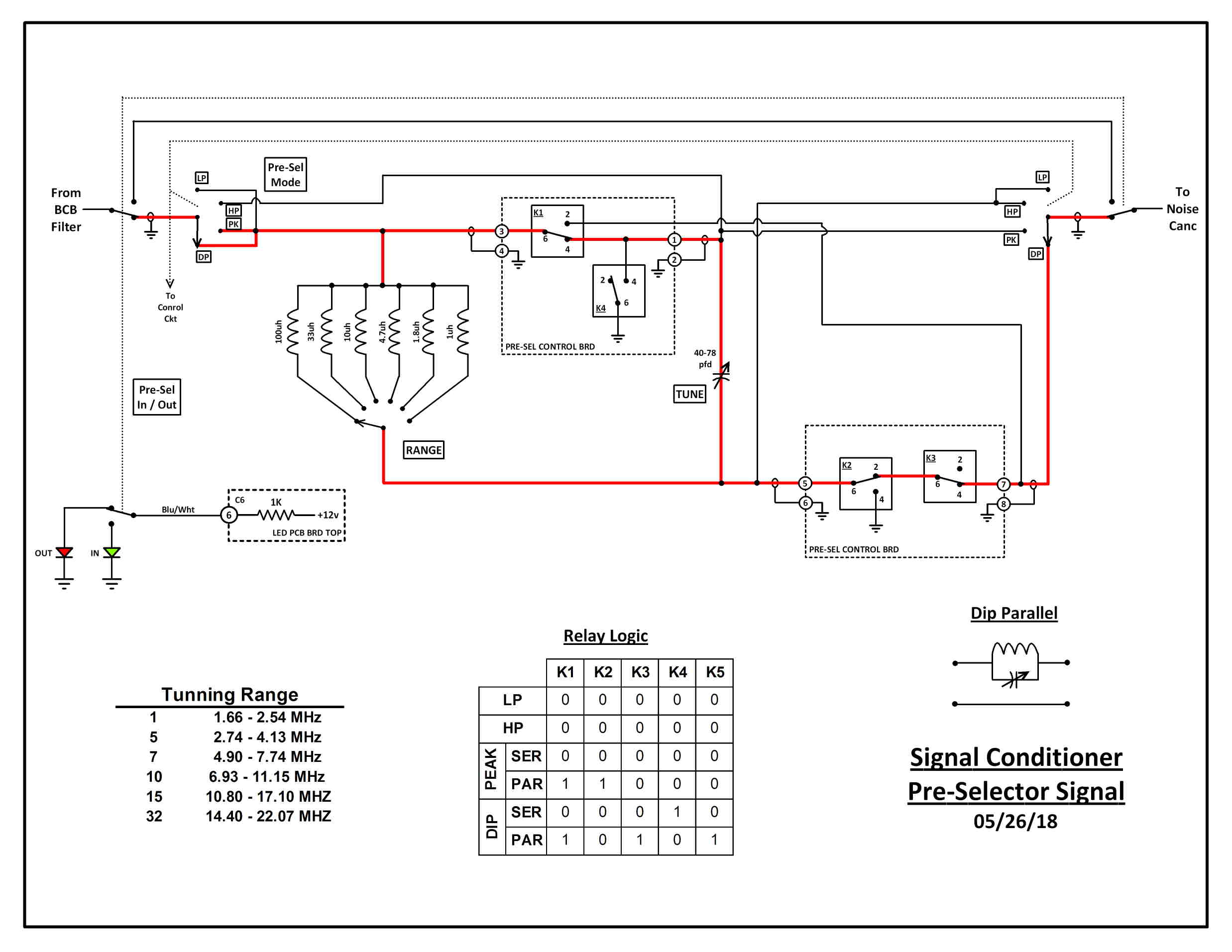
I've divided this schematic into two parts. One that shows the signal flow part of the pre-selector and one that shows the control part of the pre-selector. This is the signal flow part of the circuit. I put the most time in the pre-selector circuit both the signal part and the control part. I wanted to use a single variable cap and switchable inductance to perform all the functions I wanted in the pre-selector. This was also the only circuit I did not pilot before construction and I paid for it. I went strictly by confidence in my math. After completing the construction of the project and doing performance testing I discovered what a mistake I made. There were errors in my math and in the values I used in my math. I had way to much reactance both inductive and capacitive. It did not perform at all like I expected it to. I ended up having to pull it apart are re-design and re-build this circuit. I used a much smaller variable capacitor and had to change out all the inductors to smaller values. The problem I had was I had already labeled and clear coated the front panel with range values and they could not be changed now. So I not only had to find values that worked correctly but try and match up the response to the front panel range numbering I had already done. If I could change the range numbering on the front panel I would have made it 1,3,5,19,15 and 20. The configuration of the LC components is determined by a combination of the Pre-select mode swith, the series-parallel switch, and 5 relays. Below set of schematics show the signal flow configuration for the different positions of the pre-selector mode switch.
 
LOW PASS
 
HIGH PASS

PEAK - SERIES LC
 
PEAK - PARALLEL LC
 
DIP - SERIES LC
 
DIP - PARALLEL LC
PRESELECTOR CIRCUIT - CONTROL
This is the control part of the pre-selector that determines the configuration of the LC components. Spent 4 months spanning one summer working out the design for controlling how the LC components of the pre-selector get configured. Did a lot of trial and error design sitting on the back porch working out this circuit. But I finally came up with a working design.
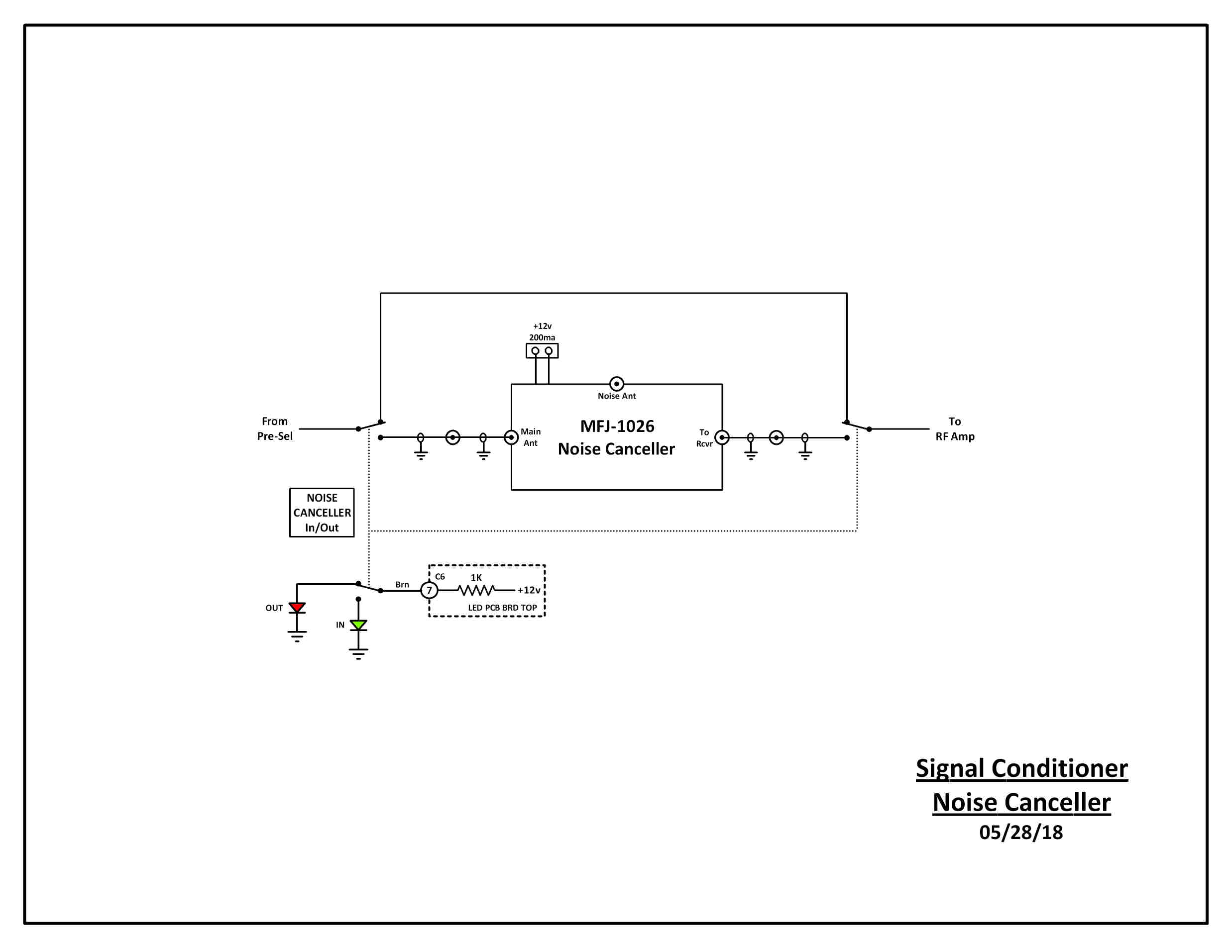
NOISE CANCELLER
Bought this on ebay some time ago, was a real good price and when I got it I knew why. It did not work properly. Doing some troubleshooting I found that T3 was not wired correctly and it looked like it came from the factory that way. This led me to believe this guy got hold of some factory rejects and sold them on ebay. Corrected the wiring and it works really well. This circuit was pretty straight forward. It's either in line or bypassed. View the MFJ-1026 tech manual and schematic.
RF AMP
The primary purpose of the RF Amp is to compensate for the insertion losses through the signal conditioner. It does give some additional gain beyond over coming insertion losses. The basis of the circuit is from the MFJ-959 Antenna Tuner. I did experiment with a number of different transistors though. I found that strong signals tend to blow the 2N3904 MFJ used. I settled on a 2N4124.
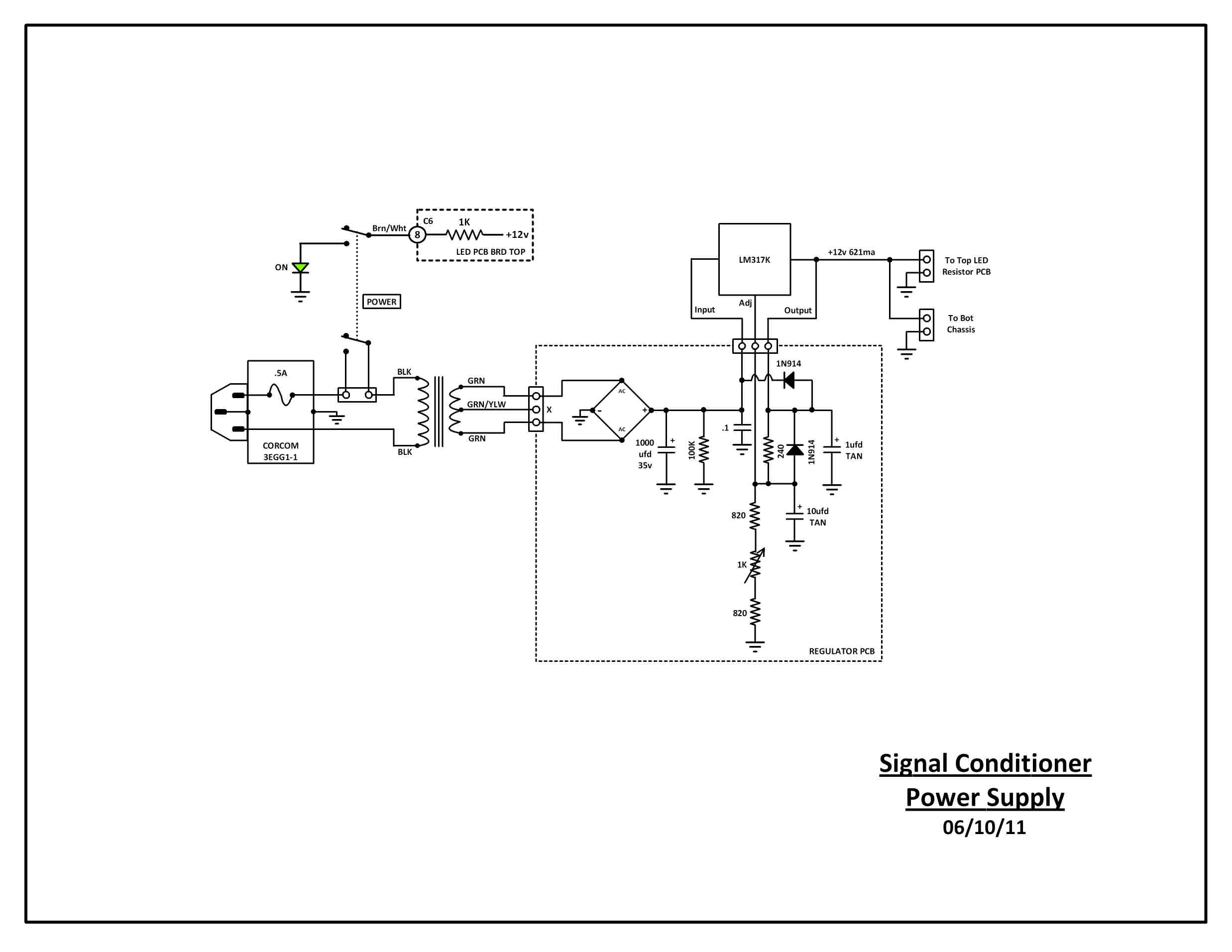
POWER SUPPLY
Power Supply is a pretty conventional LM317 supply. Nothing special.

Building The Conditioner

I built the bottom half chassis first. Front and Rear views above. The lower chassis was a reuse of an old chassis I had laying around. I had to plug holes on the back panel that were from the original chassis.  Bottom chassis consists of the Preselector Control circuit board and the bottom LED resistor board for the LED's on the lower half of the front panel.

The top half of the conditioner was built next. It was built on the top cover for the bottom chassis. All the top chassis panels I fabricated from aluminum angle stock and sheet aluminum. Top half contains the Power Supply, the top LED resistor board, the BCB filter, and the 1220 Trap. The top is also where the Noise Canceller is mounted.

Next build was the front panel. Drilled all the holes, applied the labels, and painted the front panel with clear coat. For Labeling I used dry transfer rub on's. Mounted the parts and did all the wiring. I connectorized all the modules so that all the pieces could be assembled and disassembled without soldering.

A last view of the front panel wiring close up.

Here's a couple shots of all the pieces built and ready to assemble.

First two pieces joined together are the lower chassis and the front panel.

Couple close up views of the Front Panel to lower chassis wiring complete.

Couple views of joining the top half chassis to the bottom half chassis.
 

Front panel now joined and wired to the top half chassis.

Project complete front and rear views.

And finally a picture of the completed project lit up.

Performance

Click here for the Excel Sheet with my Performance Measurements.


Top of the Project Page

Home