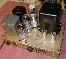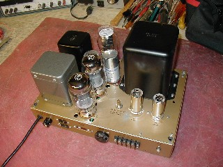
Heathkit W5M Amp Rebuild

|
Picked this up on Ebay in Late May 2008 to go along with the Hallicrafters ST-83 I recently rebuilt. It was in pretty good shape upon receipt and looked like it had been sitting for a long time so I didn't fire it up and test it. I worried about the condition of the electrolytics and went right into tearing it down for the rebuild. Wish I would have taken some before pictures but I didn't. As I contemplated my method of attack for the rebuild I started tearing it down and before you know it I had it completely tore down with no pictures taken. Circuitry was not that complicated so I didn't anticipate needing pictures for the rebuild. |
 |
 |
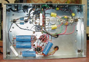
| I replaced all the caps and the resistors with the exception of the two 30 ohm 1/2% cathode resistors in the final PA. I replaced the 12AU7 sockets with Teflon silver sockets. One of the original KT66's was bad as well so purchased a new matched pair set from SRS. I purchased all the caps and resistors from Antique Electronics Supply. The resistors are all metal film resistors. I made all the mating resistors in the balanced part of the circuit from the phase splitter to the output match, not just the pairs specified in the schematic. So all the mating resistors in the balanced part of the circuit are matched pairs. For the half watt resistors in the balanced part of the circuit I used 1% resistors that I matched by flowing current through them, not just an ohms check. All the larger resistors in the balanced sections are 2% that I matched by current flow as well. All the coupling caps are high quality Auricaps. I even went through a large number of 12AU7's and matched the two triodes within the tube for the driver. All in an attempt to get as good a balanced circuit as possible in the amp. I replaced the 5R4 rectifier with an 5U4. I did make a couple changes from the Heath assembly instructions. | |
| Assembly changes:
1. I altered the wiring in the 6.3vac filament lines. Heath instructions had you wiring filaments to the V4 and then from V4 going to the options connector and then on to the 12AU7 filaments. I used V4 as a launch point for the filaments. I wired a separate pair of filament lines to the options connector and then another separate filament pair from V4 to the 12AU7's. I didn't like the idea of having option filament current plus the 12AU7 filament current running through the same little lines. Additionally, I ran the 12AU7 filament lines directly from V4 to the 12AU7 sockets rather then around the back of the chassis. Don't know that this has any advantages, just an obsessive compulsive thing on my part. 2. I changed the power supply 100 ohm dropping resistor and the 330 ohm common cathode resistor in the PA output to 10 watt resistors vs 4 watt and 7 watt respectively. Glad I did as that common cathode resistor does get very warm. 3. I changed the location of the 330 ohm common cathode resistor. Heath wired it down on the chassis buried in with the filament lines. I had a real problem with this as I didn't like having that power resistor getting hot buried in among the filament lines. A little more on this latter. I raised it up away from the chassis and wiring to get it away from the filament wires and let some air flow around it. 4. I installed a three prong power plug with ground line to the chassis. Safety. |
| Operation:
Firing it up and checking that everything worked properly went well. Outputs balanced very easily. I hooked up the Hally ST-83 and a speaker and it sounds GREAT! I am really very happy with the audio quality it produces. I measured all the voltages and ripple, all voltages were right on, ripple was very low, really low, had the scope all the way down the smallest input and was just able to see the ripple. Ran into a problem though. I set it up on the back deck and proceeded to BBQ and drink a few bears with my new amp. It was also a heat test as it ran for 6 hours on the back deck as we enjoyed the evening outside. I noticed that the power transformer was getting really, really, hot. Then as I was standing there just looking at it I noticed a tiny little whiff of smoke that appeared to come off the transformer. Oh s**t! Shut it down. Next day started testing. There were no visible smoked parts. I fired it up on the bench and it worked just fine. I then started taking current flow measurements in the power supply suspecting something was drawing some excess current to make things so hot. Test setup was input grounded with a shorting RCA plug and output into a 4 ohm dummy load. I figured the current flow in the PA's first using ohms law on the 330 ohm cathode resistor. I came up with 93ma current which meant roughly 45ma in each output tube. This seemed reasonable to me. Next I put an ammeter in the secondary center tap to measure total current flow from the plate supply. I read a steady 120ma. Schematic indicates a max of 140ma so that should be okay, I'm sure the other 20ma would be consumed by whatever is connected to the options connector. So all was well within limits. I then assumed the transformer was just old and has seen better days. I did calculate and measure some other parameters. Input power to the amp is approx 104watts. So with 25 watts of output power the amp has an efficiency of 25%. 75% wasted power as heat but that's doesn't surprise me in a totally class A amp. As excepted the current flow in the in the plate supply lines stayed virtually rock solid at 120ma from no input idle to 25watts output. So I concluded that it must just be an old tired power transformer. I figured until I found a replacement I would be limited to running it only a couple/few hours at a time. So I started playing with it on the bench pumping signals into it, looking at square waves through it etc, just to make sure it would hold up for a couple hours at a time. The next day I fired it up again just to let it run a few hours to double check and low and behold, I witnessed another little whiff of smoke. It came up through the vent holes on the chassis. Just a little whiff. Shutdown immediately. What was important about the sighting this time was I was in a lighted environment and actually saw that it came from under the chassis and NOT from the transformer as I thought I saw when it was on the deck and dark out (and a couple beers). I discovered that the filament wires buried down in that area between V4 and V3 (the place were Heath also wanted me to bury the 330 ohm cath resistor) were crispy. Additionally, it was the filament pair that went to the options connector. This was puzzling because there was nothing connected to the options connector and therefore there should not have been any current flow in the wires that were crisp! I removed the 330ohm resistor so I could get in there and dig around. Here's what I found and my theory of what happened. Those filament wires looped around some of the mounting screws. I believe what happened was as the 330ohm resistor gets quite hot, it softened up the insulation on the filament lines to the option connector. The softened insulation then eventually allowed a point where the wires ran by the sharp threads of a mount screw to wear through and started semi shorting the filament line to ground (I connected my filament center tap to ground by the way). This caused excessive current flow in the filaments, heated up the power transformer, and the whiff of smoke was that wire insulation. The Fix: |