.JPG)
Impedance Adapter
| I
built the Impedance Adapter in early 2015. I really love using a
Spectrum Analyzer to look at signals in the RF path of a circuit, there
is so much more information about the signal and what's going on in the
circuit with a spectrum analyzer. The problem is Spectrum Analyzers all
have a 50 ohm input impedance which would severely load the circuit when
sticking a probe in there. I needed something that had a high impedance
input so as not to load the circuit being tested and provide a 50 ohm
impedance output for connection to the spectrum analyzer. I decided to
use a tube as tubes have very high input impedance and if I used a
cathode follower circuit I could get the low output impedance of 50 ohms
I desired. I used Grayson Evans KJ7UM book Hollow-State Design as a
guide to designing the tube circuit. This is an excellent reference for
designing tube circuits, I highly recommend the book. Design |
.jpg) Here's the final design scat |
I started with a 6C4 triode. Evan's in his book used this tube as a cathode follower design example and in the end he determined that the 6C4 is not a good tube to use for a cathode follower and sure enough it did not work well. But it was a good exercise to use the formulas and prototype something before finalizing a design. I went on the hunt for a better tube to use as a cathode follower. I finally settled on the 955 acorn tube triode. I chose this tube because it was a high frequency tube in the day and it could possibly give me a greater useful frequency range I could use the adapter with. I had the specs and curves for the tube and it worked out really well using the formulas so I prototyped it and finalized the design. |
|
Construction |
||
.JPG) |
.JPG) |
.JPG) |
| I built the adapter in a 5x7x2 Aluminum project box. I enclosed the RF circuitry a shield made of copper clad printed circuit board. Plate voltage and filaments are fed into the enclosed circuit through feed thru caps. I used dry transfer decals to label the front panel and then put a coat of clear acrylic on it to protect the dry transfer decals. It really does not get that warm so I didn't make any ventilation holes. I left it on for a week and the heat was just fine. Looks really cool with the acorn tube. | ||
|
Performance |
|
 |
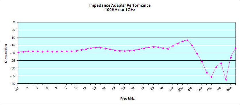 |
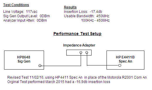
| Performance was pretty good. I plotted frequency against output level from 100KHz to 1GHz. I determined that usable frequency was from 100KHz to 450MHz. I do attribute the usability to 450MHz to the acorn tube I used. It does have an average insertion loss of -17db. Here's the full Excel data sheet if you want the full raw data. | |
|
|
|
|
|
.JPG) |
.JPG) |
| Here's front and rear view of the finished project | Here it taking it's place on the bench. Sitting next to it is an HP8447A Dual 20db Amp which I can use to bring the signal back up to compensate for the 17db thru loss. I primarily use it with the HP E4411B Spec An below it. | |
|
|
||