Home Brew Audio Switch

I completed this project in Nov 2015. My original inspiration for this project was to have a central audio switching unit I could select audio from various radios in my collection and apply the audio to a master central speaker. It was a simple concept that grew to way overkill but also way cool.

It would have 10 selectable inputs. This was based on the rotary switch I had available in the parts bin. I chose to use a line input impedance of 500/600 ohms at a reference level of 0dbm. This was chosen as many radios have a 500/600 ohm line output. I incorporated provision for radio’s that only had an 8 or 4 ohm output. I accomplished this by using 4 line transformers that would transform the 8/4 ohm inputs to 500 ohms which could then be wired into one of the available ten 500/600 ohm inputs. One of those line transformers was also setup to select between 8, 4, and 16 ohms to account for at least one input that may be 16 ohms.

I had a couple audio devices that I decided to incorporate into the project that included a Yamaha GQ1031Graphic Equalizer and a Heathkit HD-1418A Active Audio Filter. Both of these devices are switchable as either in-line or bypassed in the audio path. I have a Heathkit W5M PA used externally as the final audio PA feeding an external Jensen speaker. I needed some type of pre-amp to drive the W5M so I borrowed the Heathkit WAP2 pre-amp circuitry and built a pre-amp into the Audio Switch.

For metering I wanted to be able to monitor the input, output at the equalizer, output at the Active Audio Filter and output from the pre-amp which is also the output of the Audio Switch. I made provision for both internally monitoring and external monitoring if it was desired to connect an external AC Voltmeter for more accurate audio monitoring and signal measurement.

I added a noise generator as well that would produce both white and pink noise. This was to account for the 11th switch position available on the rotary switch, this was an overkill thing. Also added was a headphones amplifier if headphone use was desired instead of using a speaker. Muting the audio output does not mute the headphones. The headphones are always active.

Audio Switch Block Diagram
There are ten selectable 500/600 ohm audio inputs that can be either balanced or single ended. Because these input levels can be quite high from the selected radio the signal is next brought through  Daven L-Pad 500 ohm 0-38db step attenuator. The selected input then goes to the primary of a UTC LS141 600 ohm transformer. All windings on this transformer are identical 600 ohm windings and can be used for mixing or splitting. One of the secondary's goes to the metering circuit to monitor the input level. The other secondary goes to the Yamaha equalizer. This equalizer can be bypassed or in circuit. The output of the equalizer goes to another UTC LS141 transformer. One secondary from this transformer goes to the metering circuit so output of the equalizer can be monitored. The other secondary goes to the Heathkit Active Audio Filter. This filter can also be either in circuit or bypassed. The output of the filter goes to another UTC LS141. One of these secondary's also goes to the metering circuit to monitor the output of the filter. The other secondary goes to the Pre-Amp. The pre-amp is always in circuit. The pre-amp circuit is based on the Heathkit WAP2 pre-amp. The output from the pre-amp is capacitance coupled to the main output of the Audio Switch. The pre-amp output also feeds a UTC A47 500 ohm transformer which is identical to the LS 141 except its smaller. One secondary of the transformer goes to the metering circuit to monitor the output of the Audio Switch. The other secondary goes to an Aux Output for the Audio Switch and a phones amp circuit for headphone use. The phones are always live even when the Audio Switch output is muted. The pre-amp also has a noise generator built into it that provides a noise source for the 11th position of the input select switch.

Build Out

Pre Amplifier 
     
   
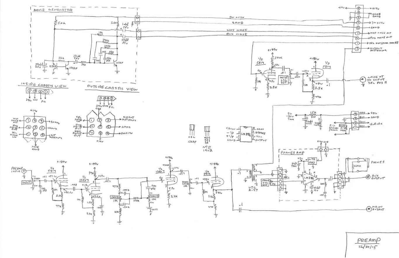
The Schematic and some shots of the pre-amp after the build. The preamp circuit is borrowed from the Heath WAP2 pre-amp. The large circuit board is the noise generator. It produces both White and Pink noise, selectable on the front panel. The smaller circuit board mounted on the side of the chassis is the phones amplifier. This amplifier uses the LM386 audio amp IC. The phones amp was a later addition after I discovered there was not enough audio level to drive the headphones. This pre-amp module bolts onto the front panel for mounting.
Power Supply
     
The power supply provides all the operating voltages for the Audio Switch. +281v for plates and +14v regulated for noise generator, phones amp, control, and LED's. As well as 12.6vac for filaments.
Front Panel 
     
     
Here's the front panel coming together. I wanted to make the front panel removable so the whole front panel is connectorized allowing it to be removed as a separate unit. Connection to an external meter for monitoring is provided on the front panel. One of the mistakes I wish I could change is I labeled the pre-amp controls under the knob, wish I would have labeled above the knobs.
Rear Panel 
       
Here's the back panel coming together. Back panel provides connections for the 10 audio inputs. It also has the connections to the impedance matching line transformers for audio inputs that are 4-8-16 ohms. For these inputs they first get wired through one of impedance matching transformers which changes impedance from 4-8-16 ohms to 600 ohms which would then get wired to one of the 600 ohm inputs to the audio switch. Back panel also provides main and auxiliary outputs for the Audio Switch. Also provided is a back panel connection for an external metering. The back panel is also completely connectorized to enable removal as a separate unit.
Cabinet  
       
Here's it all coming together in the cabinet. The cabinet originally held an R-390A that I ended up racking so I re-purposed the cabinet for this project. Cabinet was cleaned up and repainted. All the internal brackets for mounting everything where fabricated from aluminum stock. Final picture has everything in but the back panel.
Completed Unit 
   

Top of the Project Page

Home